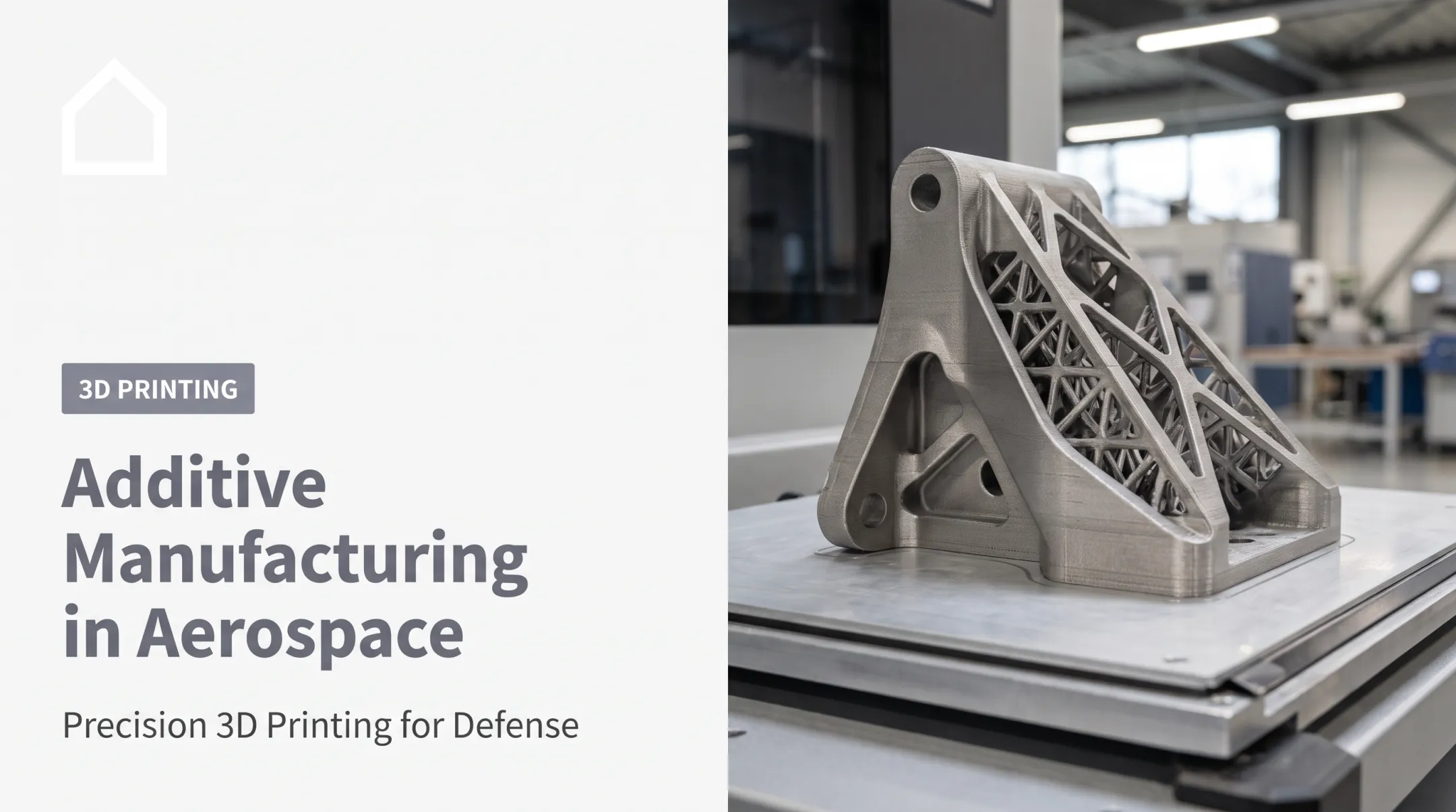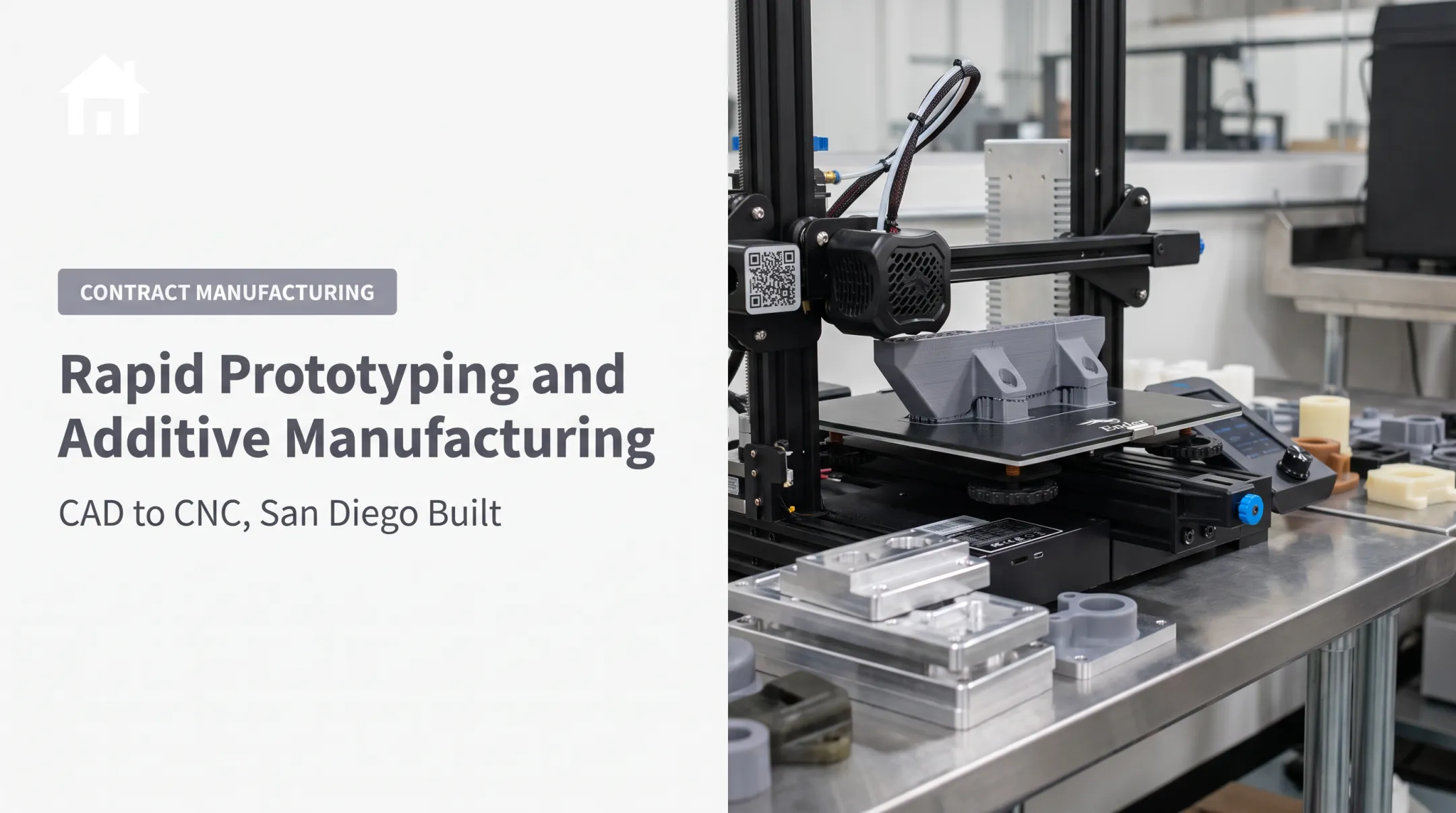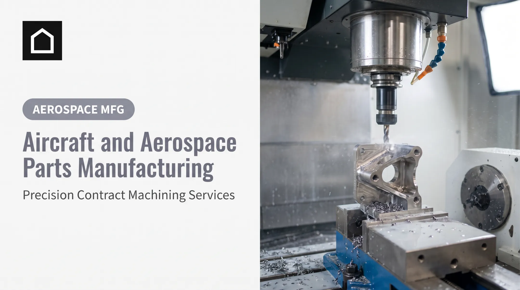

It's not a single technology. The term covers multiple processes, from polymer prototypes built overnight to metal powder-bed systems producing flight-qualified brackets. Some printed parts never leave the design lab. Others fly on production aircraft today.
This article covers where 3D printing fits in aerospace manufacturing: real applications, the materials behind them, the limitations engineers still have to manage, and how to evaluate a manufacturing partner before committing a project to print.
Key Takeaways
- Additive manufacturing excels at prototypes, tooling, and low-volume parts with complex geometry.
- Flight-critical hardware requires separate qualification — printing a part doesn't certify it.
- Match metal AM (titanium, aluminum, nickel alloys) or reinforced polymers to the part’s load and environment.
- Most aerospace programs combine 3D printing with CNC machining, casting, and molding rather than replacing them.
What 3D Printing Means for Aerospace
Additive manufacturing builds a part layer by layer directly from a digital CAD model. CNC machining does the opposite: it starts with a solid block and cuts material away until the part emerges. That distinction drives everything else: tooling needs, lead time, achievable geometry, and cost at different volumes.
A typical aerospace print project moves through several stages:
- CAD modeling and design review for manufacturability
- Slicing or toolpath generation to prepare the build file
- Printing on the selected machine and material
- Support removal and post-processing (curing, heat treatment, or machining)
- Inspection and functional testing against the part's requirements
Prototype Versus Flight Hardware
This is the line that matters most in aerospace. A printed prototype used for fit-checks or a tooling jig used in-house has very different requirements than a bracket destined for a production aircraft wing. The second case demands material allowables, process controls, and documented qualification, not just a successful print.

How Additive Compares to Traditional Processes
| Process | Geometry & Tooling | Typical Aerospace Role |
|---|---|---|
| Additive manufacturing | Builds complex, consolidated shapes directly from CAD; no dedicated tooling | Prototypes, jigs, brackets, ducting, select flight parts |
| CNC machining | Subtractive; removes material from billet, requires fixturing | Structural parts, tight-tolerance components |
| Casting | Mold-based; handles complex internal cavities well | Housings, brackets, engine components |
| Forging | Compressive shaping; efficient at high volume | Large structural members, highly loaded parts |
| Injection molding | Mold-based, highly repeatable at volume | Interior trim, connectors, non-structural brackets |
None of these processes has replaced the others. They're tools for different jobs, and most aerospace programs use several of them across one product's life.
3D Printing Applications Across Aircraft and Aerospace
Rapid Prototyping and Design Validation
Before committing to metal tooling, engineering teams print parts to check fit, airflow, thermal behavior, ergonomics, and assembly sequence. A design flaw caught in a $50 printed prototype costs far less to fix than one found after machining a production forging.
Tooling and Manufacturing Aids
Aerospace programs often start here: the parts never fly, but they support the people who build the aircraft. Common examples include:
- Jigs and fixtures for assembly alignment
- Drill guides and masking tools
- Molds, gauges, and inspection aids
- Protective caps and handling fixtures
The Department of Energy's Oak Ridge National Laboratory, working with Boeing, printed a carbon-fiber/ABS trim-and-drill tool for 777X production evaluation in just 30 hours, far faster than conventional tooling.
Interior and Cabin Components
Ducts, vents, brackets, housings, and cable-management parts are common printed applications in cabins. They are non-structural, yet they still need flammability, smoke, and toxicity (FST) ratings tied to the aircraft program and airworthiness authority.
Propulsion, Rockets, and Spacecraft
Printed parts have moved furthest into production in propulsion and space hardware:
- GE Aerospace redesigned the LEAP fuel-nozzle tip from roughly 20 welded and brazed pieces into one printed part about 25% lighter, with better durability; by 2018 it had printed its 30,000th unit
- Airbus installed a titanium pylon bracket on a production A350 XWB at the wing-to-engine junction: a flying supply-chain part, not a demo
- NASA's RAMPT program reported a printed combustion chamber and nozzle that cut thrust-chamber weight by about 40%, with production time and cost down by at least two-thirds
Research, Testing, and Spare Parts
Wind-tunnel models, sensor mounts, and test fixtures benefit from fast geometry changes between test runs. On the spares side, digital inventories sound appealing: print on demand instead of warehousing a part for 20 years.
In practice, every reprint still needs configuration control, design-file security, and inspection, because material properties and tolerances must be verified each time.

Aerospace Materials, Processes, and Design Considerations
Polymer-Based Processes
Three technologies cover most polymer aerospace work:
- FDM/FFF: affordable and effective for prototypes and tooling; layers create directional weakness
- SLA: fine resolution and smooth surfaces; typically less durable under load
- SLS: stronger parts without support structures; often used for functional prototypes and low-volume production
Metal Additive Manufacturing
Metal AM mainly splits into two approaches:
- Powder-bed fusion: fine detail within a more limited build volume
- Directed energy deposition: faster deposition for larger parts and repairs, with rougher surfaces and coarser features Titanium, aluminum, and nickel-based alloys are common for both methods. Teams choose them for strength-to-weight ratio and high-temperature performance.
Reinforced Polymers and Anisotropy
Carbon fiber and glass fiber reinforcement add stiffness, but printed parts behave differently depending on build direction. A part printed with fibers aligned to the load path performs very differently than the same part printed at 45 degrees. Design engineers should treat this anisotropic behavior as a primary constraint during design, not something discovered in testing.

Designing for Additive Manufacturing
Getting value out of AM means designing for it from the start:
- Use lattice structures and topology optimization to cut weight where loads allow
- Consolidate multi-part assemblies into single printed components
- Plan internal channels for cooling or fluid flow that casting can't achieve
- Account for build orientation, support removal access, and post-print machining
Post-Processing and Quality Steps
Printed parts rarely leave the machine ready to install. Typical steps include:
- Support removal
- Heat treatment to relieve stress
- CNC finishing for critical surfaces
- Coating, dimensional inspection, and non-destructive testing
- Documentation that ties each step back to the part
When Additive Beats Traditional Processes
Additive wins when geometry is complex, volume is low, or tooling lead time would delay a program. Injection molding and forging still win at high volume. Casting still wins for parts that need specific porosity-free structural properties at scale.
Benefits, Limitations, and Qualification Challenges
What Additive Manufacturing Does Well
- Shortens design iteration from weeks to days
- Eliminates tooling costs for one-off or low-volume parts
- Enables geometries impossible with subtractive methods
- Consolidates multi-part assemblies into fewer components, often reducing weight
GE's LEAP nozzle redesign is the clearest documented case: fewer parts, less weight, and a component now produced at scale. That's a project-specific result, not a guaranteed outcome for every printed part.
Those gains still sit inside a broader manufacturing mix.
Where Hybrid Manufacturing Fits
Most aerospace programs don't choose AM instead of CNC machining, casting, or molding. They combine them:
- Printed near-net-shape parts often still need CNC finishing on critical surfaces
- Prototypes may move from 3D printing to urethane casting for a short production bridge
- Higher volumes then shift to injection molding once hard tooling pays off
Contract manufacturers that already run CAD, AM, CNC, casting, and molding in one workflow can move a part across those steps without re-sourcing vendors at each stage.
Current Limitations
- Build envelope size restricts larger structural parts
- Production rates lag behind molding or stamping at volume
- Surface finish often requires secondary machining
- Properties can vary between machines, operators, and even build batches
- Costs rise faster than traditional processes once volumes increase
Those limits matter most when the part must clear flight approval, not only print successfully.
Qualification and Compliance
Printed parts and flight approval diverge sharply here. The FAA, EASA, and Department of Defense each maintain frameworks for additive parts, covering machine qualification, process controls, material allowables, and documentation. EASA's 2025 guidance, for instance, focuses on lower-criticality applications rather than blanket approval across all part classes.
None of these frameworks treat "it was printed successfully" as enough for flight hardware. Defense or classified programs must also account for export controls such as ITAR, which can cover design files and manufacturing instructions, not only physical parts.

Quick decision checklist before choosing additive for an aerospace part:
- Is the part structural or non-structural?
- What load, temperature, and environment will it see?
- What production quantity is expected over the part's life?
- What certification pathway applies, and who owns that process?
Selecting the Right Application and Manufacturing Partner
Choosing a 3D printing partner for an aerospace-adjacent project means asking specific questions, not just comparing printer specs:
- Which processes and materials does the shop actually run in-house?
- What tolerances and build sizes are realistic for this part?
- How are CAD files and project data protected?
- What inspection and documentation accompany each part?
- Which post-processing steps are available on-site versus outsourced?
A supplier's experience with regulated industries (medical devices, military components) is a reasonable signal of process discipline. It is not the same thing as aerospace flight-hardware certification, and no responsible shop should imply otherwise.
Stronger evaluations cover the full workflow, not only the printer:
- CAD support and design-for-manufacturing review
- Prototyping, post-processing, and CNC finishing
- Inspection, documentation, and a clean handoff toward production
Finine Design and Manufacturing, based in San Diego, runs that concept-to-production path in-house. Services include CAD modeling, 3D printing, CNC machining, urethane casting, injection molding, and production painting.
That single-partner model cuts vendor handoffs on aerospace-adjacent work. Teams should still confirm inspection scope and documentation for each job rather than assuming flight-hardware certification.
Moving From Aerospace Concept to Production
A practical project path looks like this:
- Define the part's function — load, environment, tolerance, expected quantity
- Build or revise the CAD model, incorporating design-for-manufacturing feedback
- Select a process and material matched to those requirements
- Print a prototype or tooling aid and validate fit, form, and function
- Inspect, test, and refine the design based on results
- Determine qualification needs before any flight-hardware decision
What to Bring to a Manufacturing Discussion
Come prepared with:
- CAD files
- 2D drawings with critical dimensions and tolerances
- Material requirements and surface finish needs
- Expected operating environment
- Target quantity
- Schedule or controlled-data restrictions
The more complete this package, the faster a shop can quote accurately.
Finine Design's path — Prototype → Bridge Production → Production — mirrors how these projects actually move.
A part might start as a 3D-printed prototype, move to urethane-cast bridge production for a short run while hard tooling is built, then shift to injection-molded or CNC-machined production parts. One vendor stays with the program, so you never re-explain the project from scratch.
3D printing earns its place in aerospace manufacturing when the process matches the part's purpose, its performance requirements, its production volume, and its qualification pathway. When that match is right, additive manufacturing saves real time and cost. When it isn't, you have spent more than you needed to for a prototype.
Frequently Asked Questions
How is 3D printing used to make aircraft parts in the aerospace industry?
Aerospace manufacturers use it for prototypes, tooling, interior components, spare parts, research hardware, and select production parts like engine brackets. Flight-critical components still need separate FAA or program-authority qualification before installation.
How does NASA use 3D printing?
NASA has printed rocket injectors, thrust chambers, and nozzles for propulsion research, including a chamber design that cut weight by about 40%. It has also tested printed tools aboard the International Space Station, outside commercial flight approval.
Does SpaceX use 3D printing?
Yes. NASA documented a Falcon 9 flight in January 2014 carrying a 3D-printed main oxidizer valve body in its Merlin 1D engine, and SpaceX hot-fired an in-house-printed SuperDraco engine chamber in late 2013.
Are there legal restrictions on what you can 3D print?
Yes. Limits can include intellectual property rights, export controls such as ITAR for defense-related technical data, and safety rules tied to the end use. Consult legal or compliance counsel before work on regulated or defense-related hardware.