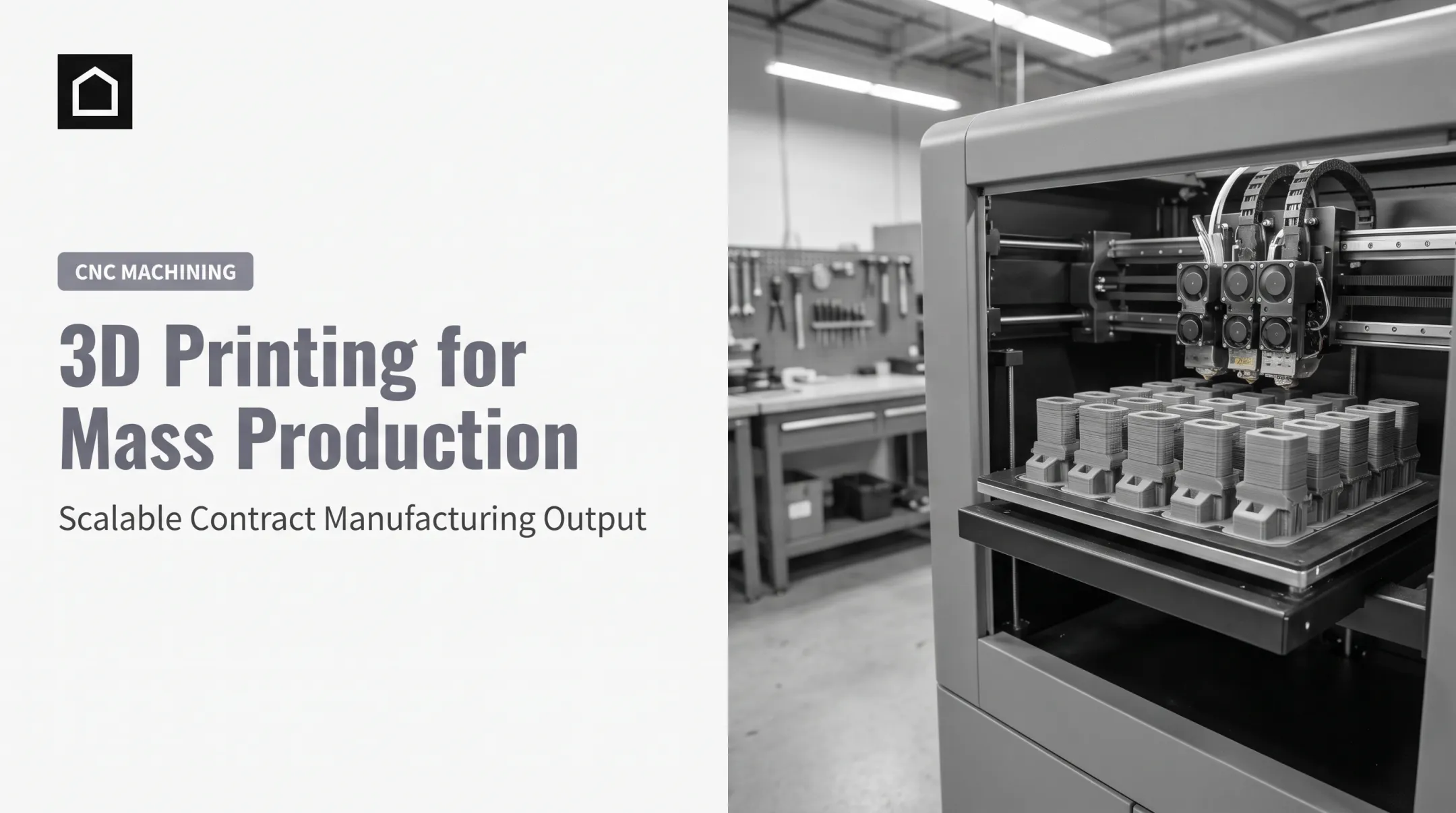

Engineering and manufacturing teams face real decisions here: which process fits the part, how to control variation across a build, what tolerances are realistic, and when a printed part actually needs machining afterward. Speed and cost pull in one direction; dimensional control pulls in another.
This guide breaks down precision terminology, the variables that actually move dimensions, how to select a process and material, what quality control should look like, and how to vet a manufacturing partner before you commit a production run.
Key Takeaways
- Accuracy, precision, resolution, and tolerance are four different concepts — know them before specifying a part.
- Material behavior, orientation, calibration, and post-processing all shift final dimensions, often more than the printer itself.
- The right process depends on function, material, quantity, and finish, not the smallest available layer height.
- Industrial 3D printing earns its keep on complex, customized, low-volume, and tooling applications.
What High-Precision Industrial 3D Printing Means
Industrial 3D printing differs from hobbyist printing in scope, not just scale. It uses production-grade equipment, engineering-grade materials, controlled process parameters, documented workflows, and quality verification before a part ships.
A desktop printer running consumer filament with no calibration record is a different category of manufacturing entirely.
Accuracy vs. Precision vs. Resolution
These three words get used interchangeably in marketing copy, but they answer different questions:
- Accuracy: how close a finished dimension is to the intended CAD value.
- Precision: how consistently the same dimension repeats across multiple parts or builds.
- Resolution: the smallest feature or layer increment the machine can physically produce.
A machine can repeat a wrong dimension with impressive consistency. That's precision without accuracy, and it's a real failure mode in production environments.
Tolerance, meanwhile, is the allowable variation assigned to a specific feature, not a single number for the whole part. Holes, mating surfaces, thin walls, flatness, and concentricity each deserve their own tolerance callout rather than one blanket spec slapped across the drawing.
Why Minimum Feature Size Isn't the Same as Part Tolerance
Here's where buyers get tripped up. A metal powder-bed-fusion brochure from 3D Systems lists a 200-micrometer minimum feature size alongside a separate typical accuracy figure of ±0.1–0.2%, with a ±100-micrometer minimum. Those are two different specifications answering two different questions.

Minimum feature size tells you the smallest detail the machine can resolve. Accuracy tells you how far a finished dimension might deviate from the CAD model on that specific machine. Neither one certifies every geometry, every alloy, or every orientation at a single blanket tolerance.
The practical takeaway: ask for the achievable tolerance on your feature, in your material, at your part size, not the printer's resolution spec.
At Finine Design and Manufacturing, design and CAD reviews work through wall thickness, draft angles, undercuts, radii, and fit before a part ever gets printed. That is where tolerance problems get caught early instead of after a build.
The Precision-Speed-Cost Tradeoff
Dialing in the finest possible settings isn't always the right production call. Finer layers and slower scan speeds drive up build time and material use, and you may still need post-processing to hit a functional tolerance.
The better question is what each feature needs to work—not how fine the machine can go on paper.
Factors That Determine Part Precision
Plenty of variables shift a part's final dimensions well beyond what the machine's spec sheet implies.
Machine and Process Control
Frame rigidity, axis movement accuracy, nozzle or laser spot size, and recoating consistency all affect repeatability. NIST's own research into laser calibration for powder-bed fusion highlights how laser spot position and power synchronization need active calibration. This isn't a "set it and forget it" process.
Bed alignment, exposure settings, temperature control, and powder or resin handling all require ongoing management, not a one-time factory setting.

Material Behavior
Materials move during and after printing:
- Shrinkage as resin cures or metal cools
- Thermal expansion during use, especially near heat sources
- Warping from residual stress, particularly in metal builds
- Moisture absorption in certain polymers
- Anisotropic strength, with parts behaving differently depending on load direction relative to layer lines
Formlabs' own dimensional accuracy study for SLS parts tests build position and orientation specifically because those variables change outcomes measurably.
Design and Orientation
How a part sits on the build plate changes everything:
- Overhangs and bridges may sag without adequate support
- Thin walls can warp or under-cure
- Holes and internal channels often print undersized and need reaming or drilling
- Stair-stepping on curved surfaces depends on orientation relative to the layer direction
- Support structures leave witness marks that need removal
Environment and Post-Processing
Ambient temperature, humidity, airflow, and vibration all matter more for some processes than others. Resin systems are notably sensitive to temperature swings during cure.
Post-processing steps like depowdering, washing, heat treatment, sanding, and CNC finishing all change dimensions, sometimes intentionally. A tolerance achieved after machining a critical surface should never be presented as the as-printed capability.
Selecting the Right Industrial 3D Printing Process and Material
No single process wins across the board. Each family has strengths tied to specific part requirements.
| Process | Best suited for | Watch out for |
|---|---|---|
| Vat photopolymerization (SLA/DLP) | Fine detail, smooth surfaces, visual prototypes, dental models | Resin aging, limited mechanical durability |
| Powder-bed polymer (SLS/MJF) | Complex nested geometries, functional prototypes, housings | Surface texture, powder removal |
| Industrial FDM | Larger functional parts, tooling, fixtures, engineering thermoplastics | Layer direction affects strength and finish |
| Metal additive (DMLS/SLM) | Complex metal components, lightweight structures, tooling | Support removal, heat treatment, higher process complexity |
Matching Material to Function
Material selection should follow function, not aesthetics. Consider:
- Strength and stiffness under expected loads
- Impact resistance and fatigue life
- Heat and chemical exposure during service
- Flexibility or wear resistance requirements
- Electrical properties, if relevant
- Biocompatibility, for dental or orthopedic applications
Prototype-grade materials often look right but don't perform like production materials. A visually accurate SLA prototype can crack under a load an engineering-grade nylon part would handle easily. Don't assume a pretty prototype has validated anything beyond fit and appearance.
When to Go Hybrid
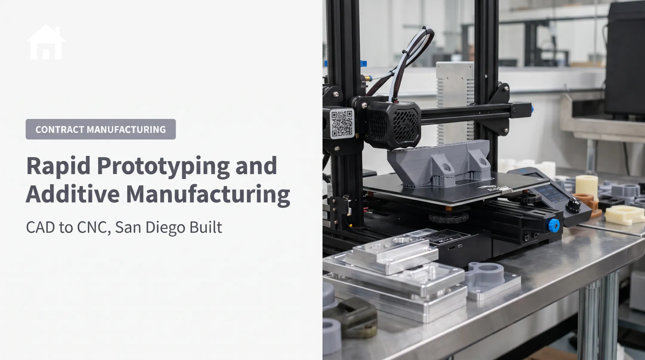
Printing the complex near-net shape and then CNC-machining the critical interfaces is often the smartest move, particularly for sealing surfaces, threaded holes, and datum features where printed tolerances alone won't cut it. Finine Design draws from CNC machining, 3D printing, urethane casting, and injection molding so the process matches the part rather than forcing one technology to do everything.
A Practical Selection Sequence
- Define the part's function and expected loads
- Identify which dimensions are actually critical to that function
- Shortlist candidate materials based on performance needs
- Choose a compatible process for that material and geometry
- Review the design for additive manufacturing constraints
- Confirm what inspection and finishing the part will need

BMW combines SLS-produced components with large-format additive manufacturing in production tooling, including a robot gripper roughly 20% lighter than its conventional counterpart.
That example is a tooling application, not a part installed on the vehicle. The distinction matters when you evaluate whether a similar approach fits your project.
Precision Printing Workflow and Quality Control
A repeatable precision workflow follows a clear sequence. Skipping steps, especially the CAD review, is where most tolerance problems originate.
- CAD review
- Design-for-additive analysis
- Quoting and process selection
- Build preparation and printing
- Post-processing, inspection, and delivery
Flag Critical Features Early
Before a part goes into production, identify:
- Datums and mating surfaces
- Holes and thread locations
- Sealing areas
- Any surface likely to need machining after printing
Choosing the Right Inspection Method
Not every part needs every inspection tool. Match the method to the risk:
- Calibrated hand measurement for straightforward dimensions
- Optical scanning for complex freeform surfaces
- CMM inspection for tight-tolerance critical features
- Surface-finish measurement when cosmetic or functional texture matters
- Material testing or NDT for load-bearing or safety-critical parts
ASTM's published standards library includes test artifacts for geometric capability and process/site qualification requirements for industrial additive manufacturing. Use them as reference points when you ask a supplier how they validate repeatability—not as a substitute for inspecting your actual part.
Questions Worth Asking Before You Commit
A supplier conversation should cover:
- What tolerance is achievable on this specific feature, in this material?
- Is material traceable to a specific lot or batch?
- What does the process-repeatability record look like?
- What inspection equipment is actually on-site?
- How are design revisions and file security handled?
Those answers only hold if the handoff is clear. Finine Design and Manufacturing accepts a 3D CAD model, ideally paired with a 2D drawing that calls out critical dimensions, tolerances, threads, surface finishes, and materials. That extra drawing is often the difference between a part that fits and one that needs rework.
Industrial Applications and Choosing a Manufacturing Partner
High-precision industrial 3D printing earns its value in specific situations, not as a universal manufacturing solution.
Where It Delivers Real Value
- Functional prototypes for design validation
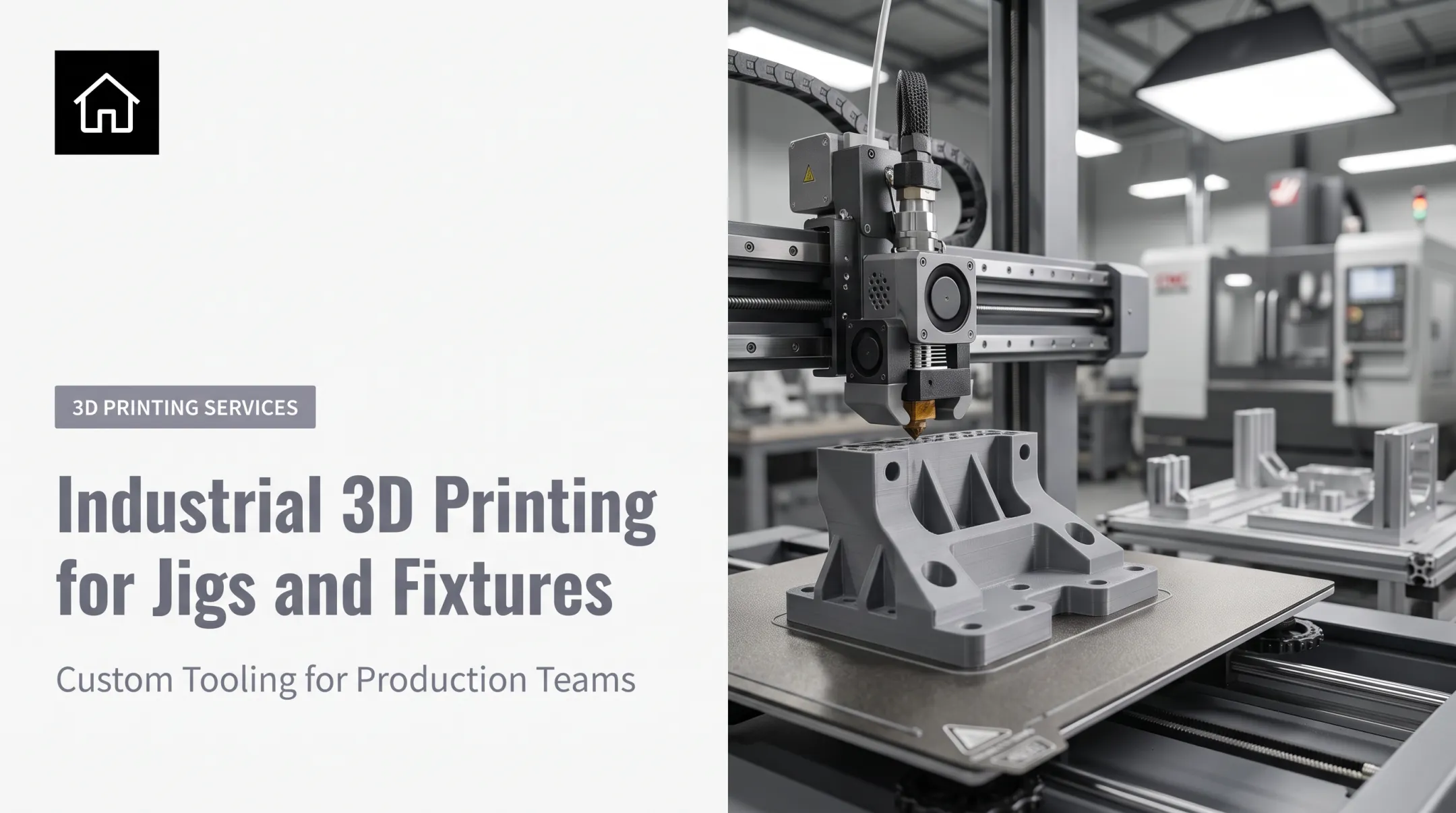
- Custom fixtures and jigs for assembly lines
- Low-volume end-use parts where tooling isn't cost-justified
- Complex housings that would be difficult or expensive to mold
- Dental and orthopedic development models
- Parts that consolidate what used to be multiple components
Fi9 Design's work spans automotive (prototypes, interior and exterior models, low-volume development parts), military and defense, consumer electronics (housings, enclosures, cosmetic and functional prototypes), and medical.
The team has particular depth in dental and orthopedic products, including anatomical training models and procedural demonstration tools.
Why Teams Choose Additive Over Tooling
3D printing reduces tooling dependence and supports fast design iteration. It handles geometries that would be impossible or prohibitively expensive to mold or machine conventionally. That said, conventional machining, casting, or injection molding still wins for higher volumes or simpler geometries where tooling cost amortizes quickly.
Fi9 Design positions itself as a one-stop development partner because the right process often changes mid-project. A part might start as a 3D-printed prototype, move to urethane casting for bridge production, then shift to injection-molded tooling once volume justifies it.
Our core capabilities span CAD modeling, 3D printing, CNC machining, urethane casting, injection molding, and production painting. That keeps the full transition under one roof instead of three vendors.
What to Share When Requesting a Quote
- CAD file and, ideally, a dimensioned drawing
- Material requirements and any performance specs
- Target quantity and expected reorder cadence
- Critical tolerances and functional features
- Intended use and finishing expectations
Reach out to Jaime at Jaime@fi9design.com or 1.858.900-9787 to start the conversation. Project scope and turnaround depend on part complexity, so send drawings early rather than describing the part verbally.
Frequently Asked Questions
How much does an industrial 3D printer cost?
Cost depends on process, build volume, materials, automation, and inspection capability. Metal systems cost far more than polymer printers. Compare total cost of ownership, including post-processing, and weigh outsourcing parts versus buying equipment.
Do industrial 3D-printed parts need post-processing?
Most do. Support removal, surface finishing, heat treatment, machining of critical features, and inspection are common. Build post-processing into timeline and cost rather than treating the raw print as the finished part.
What is the most accurate 3D printing process for industrial parts?
No single process wins for every application. Accuracy depends on geometry, material, tolerance requirements, surface finish, and post-processing. Always confirm capability against your drawing's critical features rather than a general accuracy ranking.
How accurate are industrial 3D-printed parts?
It depends on process, material, part size, orientation, calibration, and post-processing steps. Request process-specific capability data and inspection results for your actual part instead of relying on a general accuracy claim from a spec sheet.
Is 3D printing suitable for end-use production parts?
Yes, for selected low- to medium-volume, complex, or hard-to-tool parts. Suitability still requires validating mechanical performance, repeatability, finishing, and any industry-specific requirements before committing to a production run.