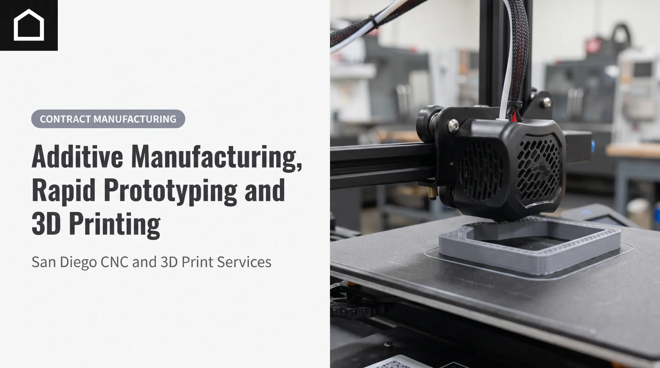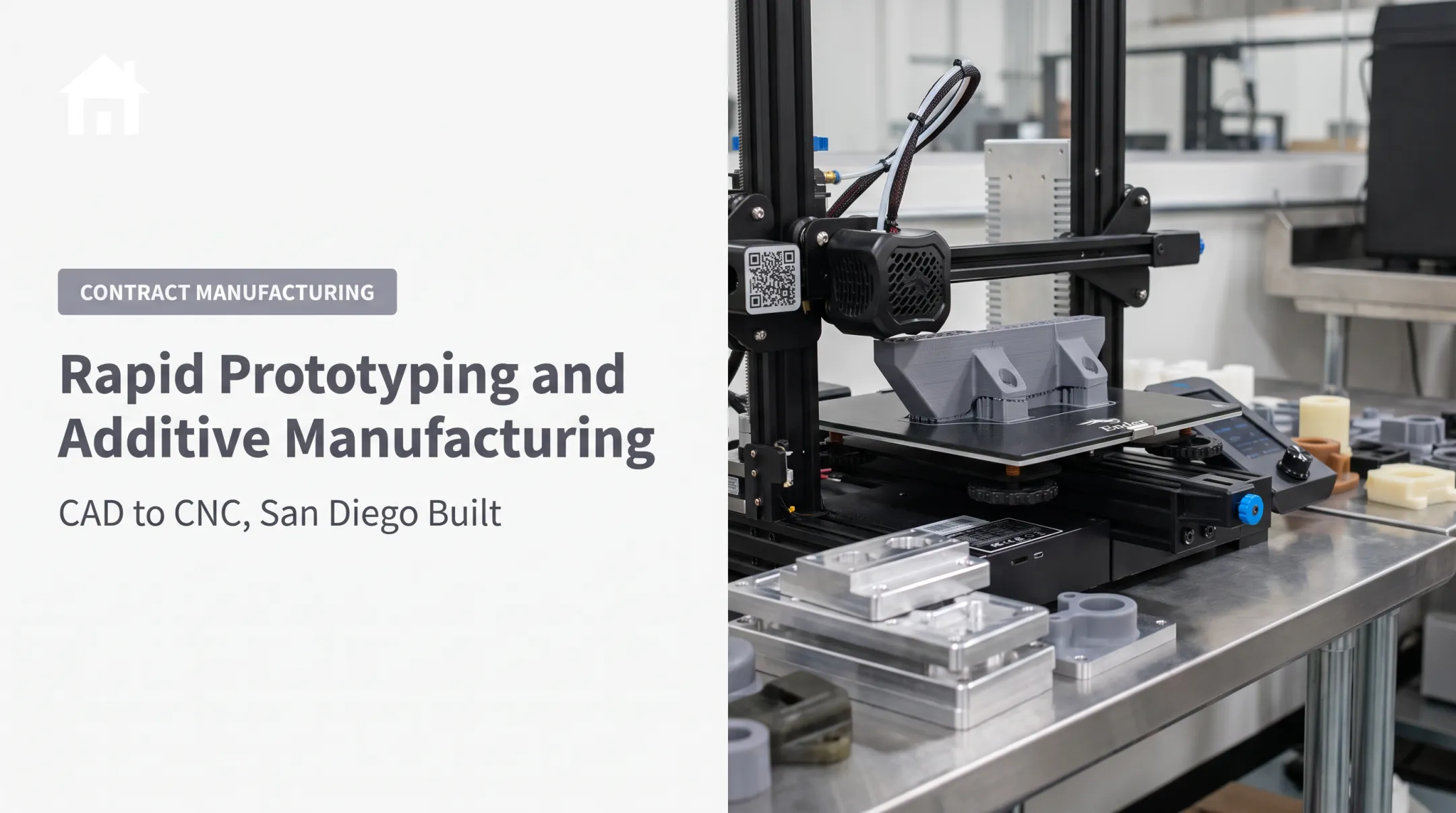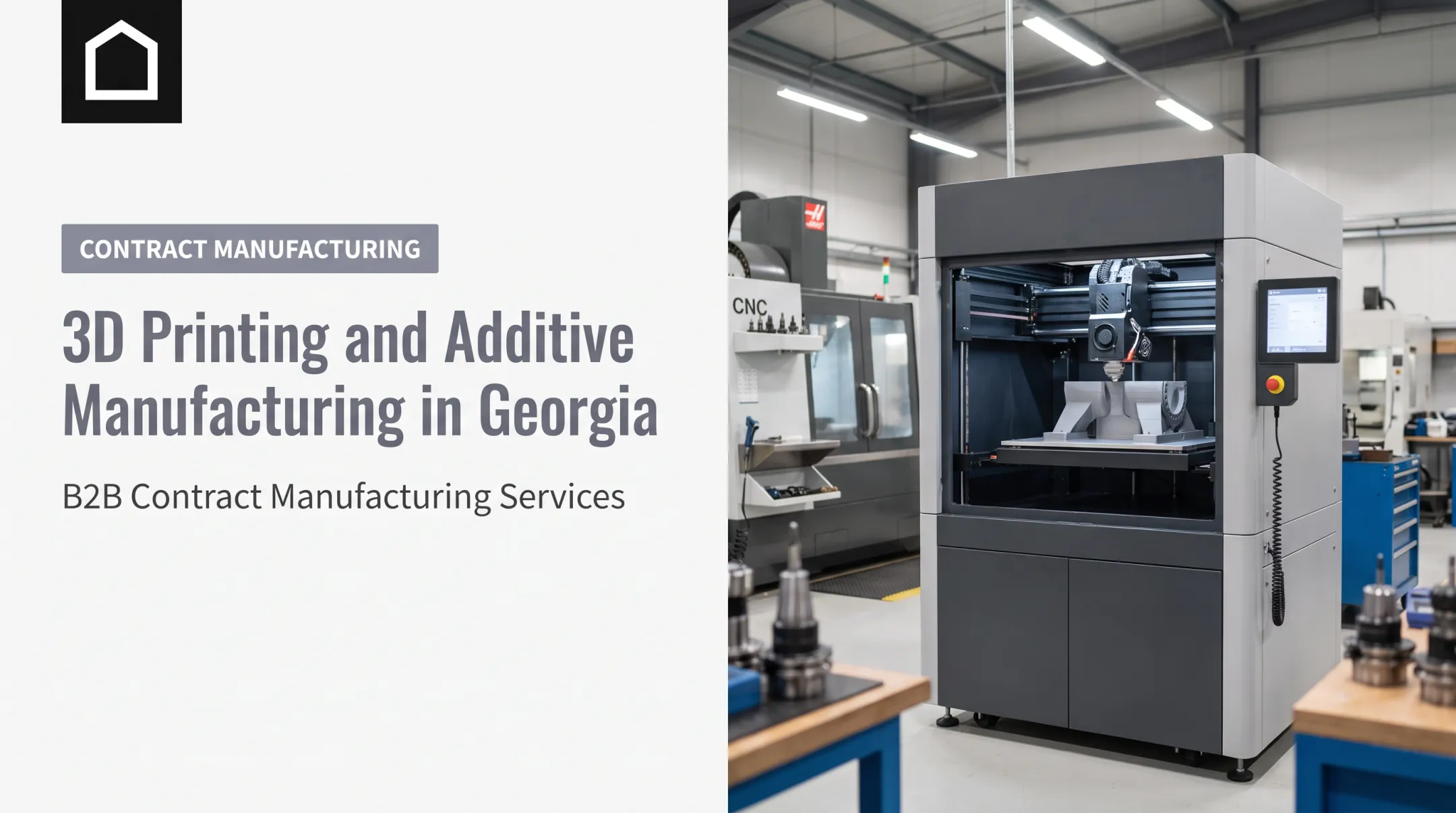

Additive manufacturing (AM) builds physical objects by adding material layer by layer from a digital design, rather than cutting a shape from a larger block. "3D printing" is the familiar name for many of these processes, but industrial AM is bigger than the machine itself.
This article covers how AM works, the major process families, where it fits in a product development plan, its real limitations, and how it stacks up against CNC machining.
Key Takeaways
- Additive manufacturing turns a CAD file or 3D scan into a physical part through a digitally controlled, layer-by-layer build
- Design freedom, fast iteration, and low tooling costs make AM strong for prototypes and select low-volume parts
- Fit depends on material needs, tolerances, surface finish, and production volume
- Hybrid workflows pair additive and subtractive methods for stronger product development results
What Is Additive Manufacturing and How Does It Work?
Additive manufacturing is the industrial term for building a three-dimensional object by depositing, curing, fusing, or bonding successive layers of material. The ISO/ASTM 52900:2021 standard defines this vocabulary precisely, and NIST describes the core distinction clearly: AM adds material, CNC machining removes it, and molding or casting shapes material using a tool or pattern.
The Digital Workflow, Step by Step
A part doesn't go from CAD file to finished component in one click. A typical build process follows this sequence:

- Start with a CAD model or 3D scan — check printability, then export as STL or 3MF
- Prepare the build — slice the model and set orientation, supports, and material parameters
- Run the build — join material layer by layer through extrusion, jetting, curing, sintering, or melting
- Post-process the part — remove supports, then wash, cure, heat-treat, or machine as needed
This sequence reflects a documented NIST reference model for powder bed fusion; not every AM technology uses every step, but the general flow holds across most processes.
Why Build Choices Matter
Part orientation, support strategy, and material choice aren't afterthoughts. EOS identifies these as core design-for-AM decisions that affect manufacturability and cost:
- Part orientation on the build platform
- Support strategy and removal path
- Material selection for strength, finish, and post-processing
NIST's test-artifact research found geometric accuracy can change based on platform position and orientation alone. Two identical files can print differently depending on setup.
That variability is where many teams stall between a good CAD file and a usable part. When an AM build later moves into CNC machining, urethane casting, or injection molding, early setup choices still shape fit, finish, and cost.
Finine Design and Manufacturing helps clients carry design intent through that handoff — from CAD modeling and 3D printing into downstream prototyping and production steps — so the part stays consistent as processes change.
Main Types of Additive Manufacturing
The ISO/ASTM vocabulary recognizes seven broad AM process families: material extrusion, vat photopolymerization, powder bed fusion, binder jetting, material jetting, sheet lamination, and directed energy deposition. Most buyers only need to understand the first three well.

Material Extrusion (FDM/FFF)
This process pushes heated thermoplastic filament through a nozzle, building up paths layer by layer. It's the most accessible AM technology and covers a wide material range, from standard plastics to engineering-grade polymers.
Layer lines are often visible on the surface. Stratasys research found mechanical properties can vary by print orientation, which matters for functional prototypes.
Vat Photopolymerization (SLA)
SLA selectively cures liquid resin with light, producing fine detail and smooth surfaces. That finish suits detailed prototypes and dental applications, as Formlabs notes in its process comparison. Most resins require washing and post-curing before the part reaches final properties.
Powder Bed Fusion (SLS and Metal Processes)
A laser selectively fuses powdered material, whether polymer (SLS) or metal (selective laser melting and related systems). This family offers strong geometric freedom, including internal channels, but requires more careful powder handling and industrial-grade equipment than desktop processes.
The Remaining Four Families
- Binder jetting deposits a binder into powder, often requiring curing or sintering afterward
- Material jetting deposits droplets of build material and can support multi-material parts
- Sheet lamination joins layers of sheet or foil material
- Directed energy deposition feeds wire or powder into an energized melt pool, often used for repair, cladding, or large metal builds
| Process | Material | Surface Finish | Typical Use |
|---|---|---|---|
| FDM/FFF | Thermoplastic filament | Visible layer lines | Functional prototypes |
| SLA | Liquid resin | Smooth, detailed | Dental models, fine detail parts |
| SLS | Polymer powder | Grainy as-built | Functional prototypes, some end-use parts |
Each process trades access, finish, and post-processing differently. FDM is accessible and material-flexible but shows layer lines. SLA delivers detail and smoothness but needs post-curing.
SLS skips support structures (the powder bed supports the part) but produces a rougher surface. Match the process to the part's requirements, not to whichever machine is closest at hand.
Naming note: FDM is a Stratasys registered trademark, while "material extrusion" is the ISO/ASTM family name and FFF is the generic equivalent. Vendor names don't always map one-to-one onto standards terminology.
Benefits and Applications of Additive Manufacturing
Faster Iteration, Less Tooling
AM shortens the path from digital concept to physical prototype largely by removing the tooling step. A documented Formlabs customer case with Productive Plastics shows a manufacturer printing in-house fixtures to solve a production-floor problem rather than waiting on an outsourced machined part. That's a case-specific result, not an industry-wide turnaround guarantee, but it illustrates the pattern well.
Design Freedom That Conventional Methods Struggle With
AM opens up geometries that are difficult or costly through traditional machining:
- Internal channels and cooling passages, documented by 3D Systems as a metal-AM application
- Lattice structures for lightweighting
- Consolidated assemblies that combine multiple parts into one print
- Organic shapes that would require complex multi-axis machining setups
When every part needs a different geometry, or when dedicated molds would sit idle after a short run, AM avoids that sunk tooling cost entirely. That payoff is strongest for small batches and one-off fixtures.
The Sustainability Picture Is More Nuanced Than It Sounds
AM can place material only where it's needed, reducing certain waste streams. But NIST's own sustainability research cautions that energy consumption, feedstock production, support material, and post-processing all factor into the full picture. A printed part isn't automatically the lower-impact choice; it depends on the process, material, and what happens after the print finishes.
Applications Across Finine's Target Industries
- Automotive — prototypes, fit checks, tooling aids, and select lightweight or low-volume replacement parts
- Military and defense — rapid iteration and specialized components, subject to applicable specifications and controls
- Consumer electronics — form studies, ergonomic testing, enclosures, and limited-run fixtures
- Dental and orthopedic — customized models and design validation, with material and regulatory evaluation handled separately
A 3D-printed prototype is not automatically suitable for a safety-critical or regulated end-use application. Finine Design and Manufacturing's prototype parts are built for development and evaluation; regulatory qualification for final use remains the client's responsibility.
Once a design is validated, Finine's broader services (CNC machining, urethane casting, injection molding, and production painting) help move the part toward the production method that actually fits.
Additive vs. Subtractive Manufacturing
CNC machining removes material from solid stock using cutting tools. AM adds it layer by layer. That single difference cascades into nearly every practical comparison.
Where the Two Methods Diverge
| Factor | Additive Manufacturing | CNC Machining |
|---|---|---|
| Material direction | Adds layer by layer | Removes from solid stock |
| Tooling | None required | Fixtures and cutting tools needed |
| Geometry | Complex internal features possible | Limited by tool access |
| Surface finish | Often process-dependent, can be rough | Generally smoother out of the machine |
| Material range | Narrower per machine | Broad range of machinable stock |
Stratasys's own technical comparison confirms CNC machining generally achieves finer tolerances and smoother surfaces than the AM processes it benchmarks. That's not a knock against AM — it's a reason to pick the right tool for the job.
When AM Wins
- Complex geometry that would need expensive multi-axis machining setups
- Low-to-moderate quantities where tooling cost would dominate the budget
- Design iteration cycles where the part changes week to week
- Lightweighting through lattice or internal structures
When CNC, Molding, or Casting Wins
- Tight tolerances paired with a demanding surface finish
- Larger production runs where per-part cost drops with volume
- Material requirements outside a given AM machine's compatible range
- Large parts that exceed typical build envelopes
The Hybrid Workflow
Many teams don't pick one or the other — they use both at different stages. AM produces a near-net-shape part or prototype; CNC machining finishes critical surfaces or tight-tolerance features. At Finine Design and Manufacturing, parts often move through Prototype, Bridge Production, and Production stages, using 3D printing, CNC machining, urethane casting, and injection molding as the design matures. A 3D-printed check piece can confirm fit against an enclosure before committing to cut aluminum stock, for example — cheap insurance against an expensive mistake.

Decision framework: weigh volume, part complexity, material requirements, tolerances, lead time, tooling budget, and surface finish together. No single factor should decide the process on its own.
Limitations and How to Choose an AM Process
AM has real constraints, and they should shape process choice from the start.
Common Limitations
- Anisotropic properties — Stratasys research confirms mechanical strength can vary by print orientation
- Dimensional variation — NIST test-artifact data shows accuracy can shift based on build platform position
- Surface texture — ranges from grainy (SLS) to layer-lined (FDM) depending on process
- Support removal — adds labor and can leave marks requiring additional finishing
- Build envelope limits — machine capacity constrains part size
Quality Depends on the Whole Chain
Final part quality depends on the full production chain, not the printer alone:
- Design for additive manufacturing
- Calibration and build parameters
- Material storage and handling
- Operator expertise
- Inspection and process control
Standards like ISO/ASTM 52920:2023 cover qualification principles for industrial AM processes. ISO 13485:2016 sets quality-management requirements relevant to medical device organizations.
A Practical Selection Checklist
Before committing to a process, define:
- The part's function and operating environment
- Material and temperature requirements
- Mechanical loads it needs to withstand
- Tolerances and surface finish expectations
- Quantity and customization level needed
- Delivery timeline and regulatory documentation requirements
For parts headed toward medical, defense, automotive safety, or other regulated applications, get professional process guidance early. Process suitability and regulatory approval are two separate things — passing one doesn't guarantee the other.
If you have a product concept ready, work with a partner who can evaluate AM alongside CNC machining, urethane casting, injection molding, and finishing options before you lock into one path.
Frequently Asked Questions
What are SLA, SLS, and FDM?
- SLA: Cures liquid resin with light (vat photopolymerization)
- SLS: Fuses polymer powder with a laser (powder bed fusion)
- FDM: Extrudes heated thermoplastic filament (material extrusion)
Each differs in feedstock, surface finish, and typical application.
What is additive manufacturing vs. 3D printing?
The terms are often used interchangeably. Additive manufacturing refers more broadly to the industrial process, including design preparation, material selection, post-processing, inspection, and production planning.
Which is better, FDM or SLA?
It depends on the part’s required detail, surface finish, material properties, durability needs, size, budget, and post-processing tolerance. Match the process to those constraints rather than ranking one as best overall.
Is CNC harder than 3D printing?
Each has its own complexity. CNC machining requires programming and tooling setup; 3D printing requires build preparation and post-processing. Which feels harder depends on the part geometry, tolerances, and your team’s experience.
Can you explain 3D printing in a simple way?
Think of it as building an object one thin layer at a time from a digital model, almost like stacking very thin slices until they form the whole shape. The exact method depends on the printer and material used.
What is another name for additive manufacturing?
3D printing is the most common alternative term. Rapid prototyping and rapid manufacturing name specific use cases, not the full technology.