
Introduction
A machined jig takes weeks to design, quote, and deliver. By the time it arrives, the part geometry it was built for may have already changed.
That delay is the quiet cost of conventional tooling: slow revisions, tied-up machine shop capacity, and inventory of fixtures nobody uses anymore.
Industrial 3D printing offers a different path. Teams can generate a custom production aid directly from CAD data, often in hours rather than weeks.
Automotive lighting manufacturer J.W. Speaker reported printed fixtures ready in 9 hours, compared to one week through its own machine shop or two weeks outsourced (Stratasys, 2025).
But speed isn't the whole story. Suitability depends on the tool's loads, environment, accuracy requirements, and expected service life.
This article covers applications, benefits and limitations, technology and material selection, design and validation practices, and how to decide between printed, machined, or hybrid tooling.
Key Takeaways
- Jigs guide a tool or operation; fixtures locate and hold a workpiece.
- Printed tooling offers faster iteration, design flexibility, and on-demand replacement.
- High-load, high-heat, high-wear, or safety-critical tools often need metal, not plastic.
- Material choice, print orientation, hardware inserts, and functional testing determine real-world reliability.
What Industrial 3D Printing Means for Jigs and Fixtures
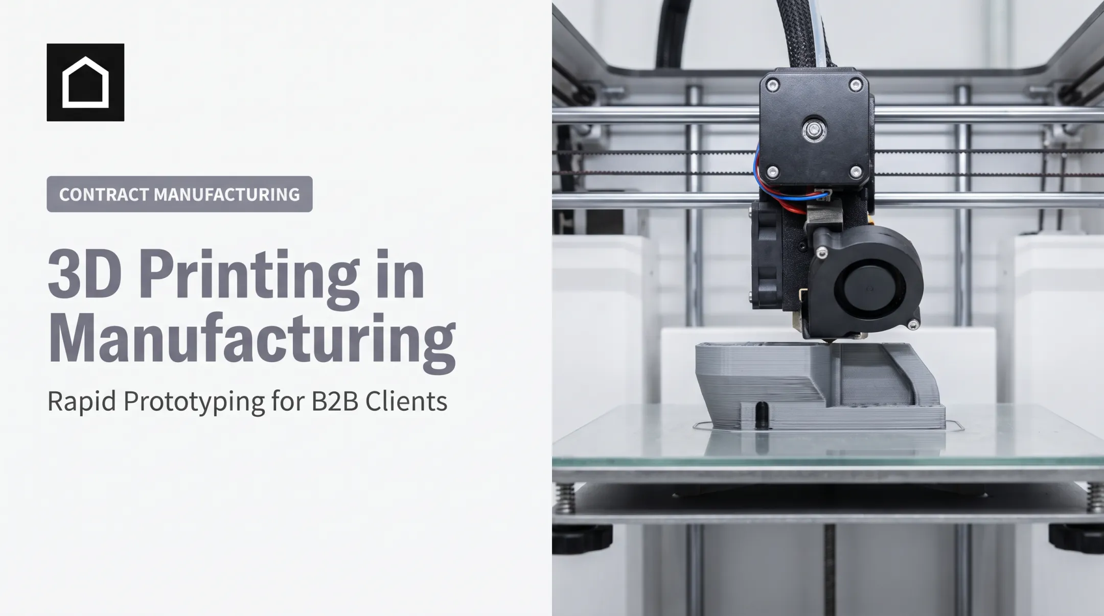
Industrial 3D printing for tooling is the additive manufacture of custom production aids from a digital CAD model. These tools are built for repeated shop-floor use—not one-off demos, hobby prints, or end-use consumer parts.
Jigs vs. Fixtures
The terms get used interchangeably, but they mean different things:
- A jig guides a tool during an operation, such as drilling, cutting, routing, or welding.
- A fixture locates and holds the workpiece itself, without guiding the tool.
- A tool that does both is technically a jig, according to SME's fixture design terminology.
Beyond the Basic Tool
Printed production aids go well beyond a basic holding block. Common examples include:
- Soft jaws and contoured nests for workholding
- Drill guides and routing templates
- Go/no-go gauges for quick dimensional checks
- Alignment and assembly fixtures
- Bonding fixtures and masking templates
- Surrogate parts used as stand-ins for real components
From CAD to the Shop Floor
A typical workflow starts with part geometry and process requirements, moves through CAD design and print preparation, then finishes with post-processing, hardware installation, fit testing, and release to the floor.

Before you pick a material or printer process, classify the tool:
- One-off prototype aid
- Repeatable production tool
- Inspection device
- Long-life fixture expected to survive thousands of cycles
That classification drives every decision that follows.
Why Manufacturers Use 3D Printed Jigs and Fixtures
Faster Replacement When Designs Change
Printed tooling pays off most on custom, low-volume, or frequently revised parts. When a product version changes, you can redesign and reprint a fixture without re-cutting a machining program.
MAHLE's automotive HVAC assembly fixture was redesigned and delivered in less than a week, versus four to five weeks estimated for conventional manufacturing (Stratasys, 2020).
Cost Beyond the Material Price
Material cost per pound rarely tells the full story. The real comparison includes:
- CNC programming and machine setup time
- Outsourcing lead time and shipping
- Minimum order quantities from outside vendors
- Spare-tool inventory, storage, and tracking
- Redesign costs every time a part revision hits
Geometry and Operator Benefits
Complex contours, conformal workholding surfaces, internal lattices, and integrated handles are often easier to print than to machine. Operators also benefit from:
- Lighter tools that reduce fatigue over a shift
- Non-marring contact surfaces for painted or polished parts
- Repeatable positioning without manual guesswork
- Visual or tactile cues that confirm correct part loading
Where Printed Tools Fall Short
Printed polymers typically have lower stiffness, heat resistance, and wear resistance than machined metal. Layer orientation also affects strength, meaning a fixture can be strong in one direction and weak in another if it's printed the wrong way.

Good candidate checklist — printed tooling tends to work well when the project has:
- Customized geometry
- Low-to-moderate production volume
- Manageable forces and temperatures
- A need for fast iteration
- Failure risk you can control with validation and a spare on hand
Applications and Use Cases
Printed jigs and fixtures show up across the shop floor in several repeatable roles:
- Workholding and soft jaws: Contoured nests, clamp pads, and soft jaws protect painted panels, polished housings, and plastic components from marring during machining or assembly
- Guidance and alignment tools: Drill guides, routing templates, and welding aids keep repetitive operations consistent; holes that see thousands of drill passes often need press-fit metal bushings rather than bare plastic
- Inspection gauges: Go/no-go and dimensional check fixtures print quickly, but plastic wears, so set calibration and replacement intervals and confirm tolerances match inspection requirements
- Assembly, bonding, and masking aids: Fixtures that lock orientation during bonding, assembly, labeling, and masking reduce setup variation versus eyeballing alignment by hand
- Surrogate parts for process validation: Printed stand-ins let teams test fit, access, sequence, and tooling clearance before risking an expensive or production-critical part
Medtronic's Warsaw manufacturing operation used printed gages, jigs, and fixtures across metrology, assembly, and quality control work on its factory floor (Stratasys).
These examples span automotive, military, consumer electronics, and medical device manufacturing. One caution: a printed production aid used in a regulated environment is not automatically approved for safety-critical or patient-contact applications. That qualification runs through the program's own quality system, not through the printer.
Choosing the Right Technology and Material
No single printing process or material wins every job. The right choice depends on the tool's loads, environment, and accuracy needs.
| Process | Best for | Trade-off |
|---|---|---|
| FDM/FFF | Larger, general-purpose polymer tooling | Lower surface detail, anisotropic strength |
| SLA/DLP | Smaller, detailed tools with smooth surfaces | Limited build size, UV sensitivity over time |
| SLS/MJF | Durable nylon tooling, complex geometries | Higher cost per part, longer post-processing |
| Metal AM / CNC | High loads, heat, or tight long-term tolerances | Slower turnaround, higher upfront cost |
Material Selection Criteria
Match the material to the application, not the other way around. Key factors include:
- Clamping and operating loads, and the direction those loads apply
- Operating temperature and humidity
- Chemical or solvent exposure
- Abrasion and expected cycle count
- Contact with finished or delicate surfaces
- Required dimensional tolerance
Heat ratings illustrate why test conditions matter. Formlabs' Nylon 12 Powder lists a heat-deflection temperature of 87°C at 1.8 MPa, but 171°C at a lighter 0.45 MPa load (Formlabs datasheet).

A tool near a heat source under real clamping force behaves very differently than the same material under a light test load.
Hybrid Construction
Material choice alone does not finish the job. How you build the fixture matters just as much.
The strongest printed fixtures often pair a polymer body with metal bushings, threaded inserts, dowel pins, or replaceable wear plates. That hybrid setup holds up better at high-wear points such as drill guide holes.
Choose the process that matches the demand:
- Print for customized, complex, low-volume, or fast-changing tools
- Use CNC or metal tooling when sustained loads, extreme heat, severe wear, or safety-critical performance dominate
Design, Validation, and Sourcing Best Practices
Design From the Workpiece Out
Start with the part CAD model, not the tool. Establish datums, locating surfaces, clamp points, tool clearances, fastener access, and the operator's loading direction before adding the printed body around them.
Design-for-Printing Principles
A few practical rules keep printed tools from failing early:
- Orient layers so the load runs with the print's strongest axis, not across it
- Add ribs and fillets at stress concentrations
- Control wall thickness to avoid warping
- Minimize unsupported overhangs
- Plan for shrinkage and post-processing from the start
Validation Sequence
Before a printed tool goes into regular use, run it through a structured check:
- Inspect printed dimensions against the CAD model
- Test fit with a noncritical part first
- Run a controlled functional trial under real operating conditions
- Check repeatability across several representative cycles
- Monitor for deformation or wear over time
- Document approved operating limits so operators know the tool's boundaries
Keeping Tools in Spec
Keep each tool production-ready with a simple control loop:
- Log revision history, material, and print settings with every build
- Set inspection intervals matched to duty cycle and load
- Remove damaged or out-of-tolerance tools from the floor immediately
When the choice is a printed fixture versus a machined one, Finine Design and Manufacturing supports automotive, military, consumer electronics, and medical device teams from CAD and 3D printing through CNC machining, urethane casting, and injection molding. Talk through the tradeoffs before you lock the process.
Frequently Asked Questions
What is the best 3D printer for industrial use?
It depends on the job. Match the process to tool size, accuracy, material, load, heat, wear, volume, and post-processing needs—evaluate the application first, then pick the machine.
Can you 3D print jigs and fixtures for manufacturing?
Yes. Drill guides, assembly aids, soft jaws, gauges, masking templates, and alignment tools are commonly printed once their operating conditions are understood and validated against real-world use.
Are 3D printed jigs and fixtures strong enough for industrial use?
For many low-to-moderate load applications, yes. High-load, high-heat, high-wear, or safety-critical tooling often needs reinforced polymers, metal hardware, or CNC-machined components instead.
What material is best for 3D printed jigs and fixtures?
No single material fits every job. Thermoplastics suit light-duty tools; nylon and reinforced polymers handle tougher use. Flexible materials work for pads and grips, and resins suit small, detailed tooling.
When should a jig or fixture be CNC machined instead of 3D printed?
Choose machining when the tool faces severe loads, extreme heat, high wear, strict long-term tolerances, high cycle counts, or safety-critical requirements that a printed polymer can't reliably meet.