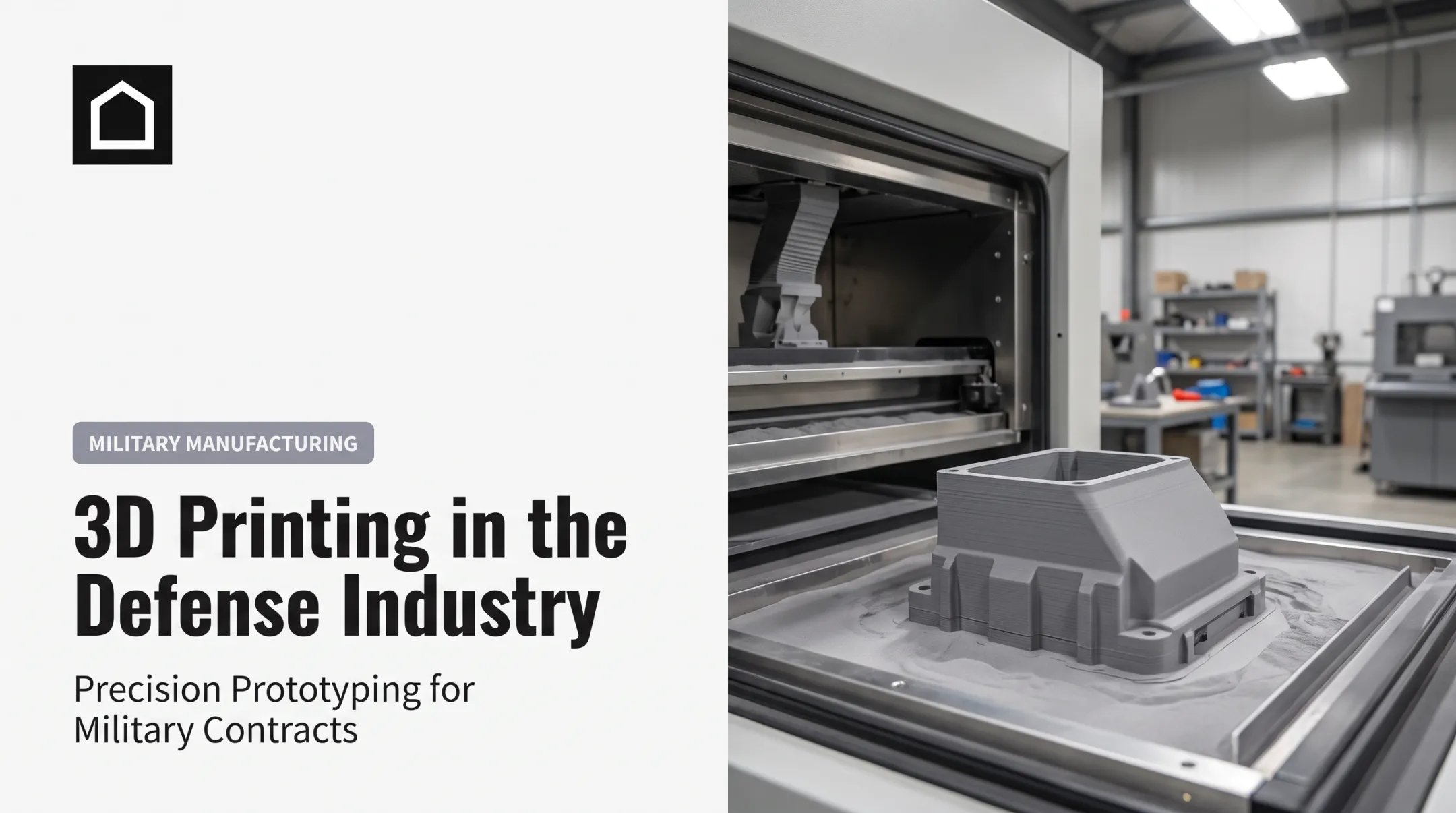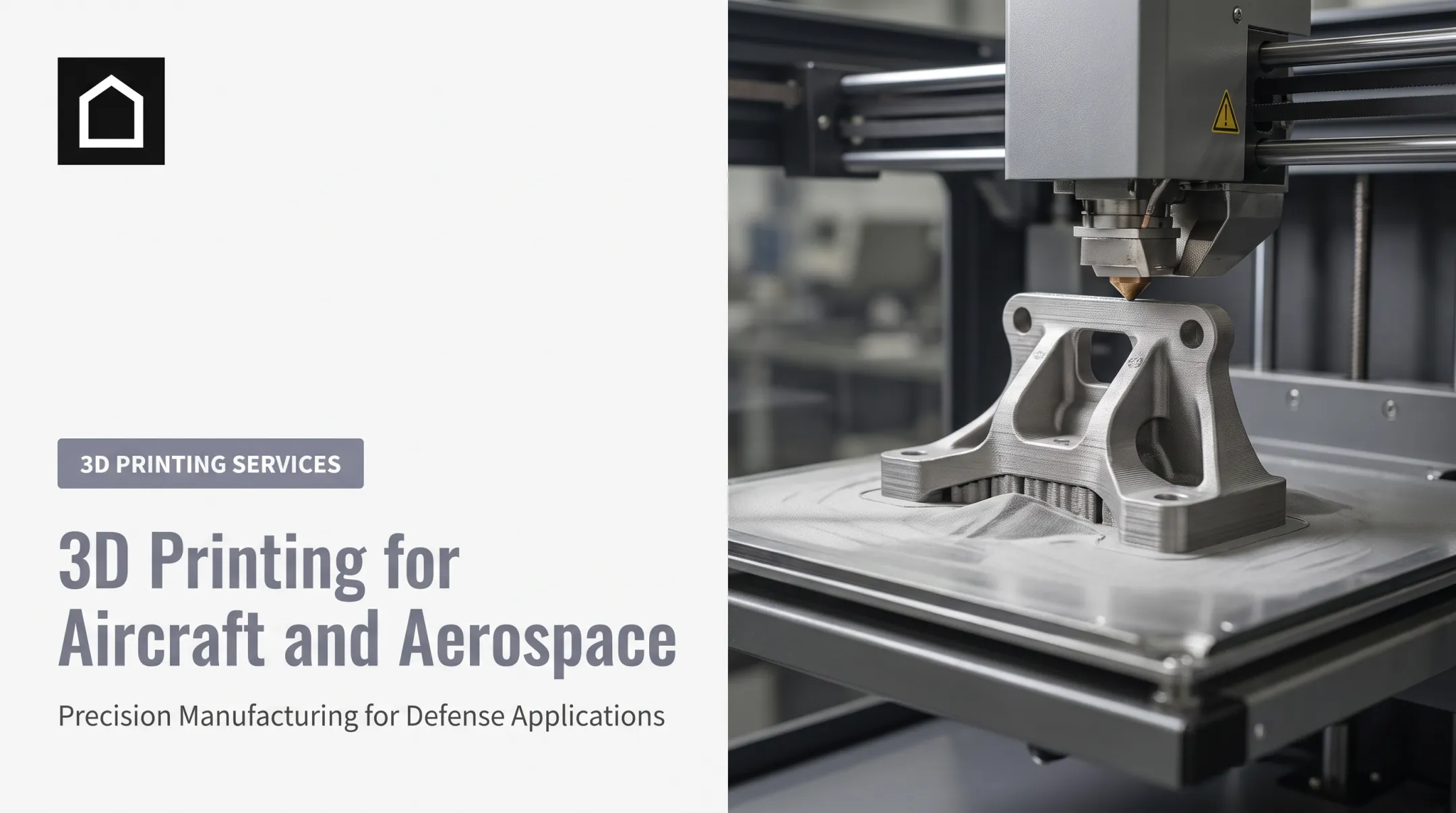

This article covers aerospace AM fundamentals, applications, processes, materials, benefits, constraints, and qualification considerations. It's written to help you determine whether your project is actually a good fit.
One distinction matters more than any other: AM used for a prototype has almost nothing in common, documentation-wise, with AM used for flight-critical production hardware. Tooling, replacement parts, and production components each carry their own validation requirements. Confusing these categories is where most AM evaluations go wrong.
Key Takeaways
- Additive manufacturing (AM) builds complex, lightweight, consolidated aerospace parts straight from digital design files.
- Teams use AM for prototyping, tooling, cabin/UAV parts, engines, brackets, heat exchangers, repairs, and spares.
- Choose process and material by geometry, mechanical/thermal loads, build volume, and post-processing needs.
- Adoption hinges less on printability and more on qualification, traceability, and change control.
What Is Additive Manufacturing in Aerospace?
Additive manufacturing builds a physical part layer by layer from a 3D CAD file. That's the opposite of subtractive machining, which removes material from stock, or casting and forging, which shape material using molds and dies.
Aerospace AM covers commercial aviation, military and defense aircraft, spacecraft, satellites, launch vehicles, and unmanned aerial vehicles.
The Digital-to-Physical Workflow
A typical aerospace AM project moves through several stages:
- CAD modeling and design-for-AM review - the geometry gets adapted for additive-specific constraints like overhangs and wall thickness.
- Process and material selection - based on mechanical loads, operating temperature, and build volume.
- Build preparation and printing - orientation, supports, and parameters are locked in before the machine runs.
- Post-processing - support removal, heat treatment, machining of critical surfaces, and surface finishing.
- Inspection and documentation - dimensional checks, nondestructive testing, and record-keeping.
Rapid prototyping can skip most of steps 4 and 5. Production parts cannot. A flight-critical bracket needs consistent material properties across every build, not just one good print.
Why Aerospace Adopts AM
Aerospace programs face constant pressure to cut mass, shorten development cycles, and keep aging fleets flying when original suppliers have vanished. NASA's own injector program illustrates the speed advantage. A 3D-printed rocket injector reached the test stand in less than three weeks, compared with six months for the conventionally fabricated version, at roughly half the cost per unit.

That said, AM isn't automatically cheaper or better. For high-volume, geometrically simple parts, established methods like casting or injection molding often remain the more economical, better-qualified choice. AM wins where design freedom, low tooling investment, and part consolidation outweigh its per-unit cost.
Aerospace Applications and Benefits
AM shows up differently depending on where a part sits in the product lifecycle.
Development stage:
- Rapid prototypes and fit-check models that let engineers iterate before committing to tooling
- Aerodynamic test parts and functional mockups
Production support:
- Jigs, fixtures, gauges, and assembly tools built faster and lighter than machined equivalents
- Patterns for secondary processes like casting
End-use hardware:
- Brackets, ducts, housings, and heat exchangers
- Fuel-system and propulsion components
- Cabin interior parts and UAV structures
Maintenance and spares:
- Digital inventories that replace physical warehousing for slow-moving parts
- On-demand production when original tooling or suppliers no longer exist
The Real Performance Benefits
GE Aerospace's LEAP engine fuel-nozzle tip remains one of the clearest consolidation case studies in the industry. GE reduced the nozzle from roughly 20 joined pieces to a single printed part and cut its weight by about 25%, then reported its 30,000th unit in production—proof that AM can scale into repeat builds, not just one-off demos.

Beyond that example, the core benefits fall into four areas:
- Topology optimization and lattice structures cut weight by removing material that isn't carrying load
- Part consolidation replaces multi-piece assemblies with fewer joints and fewer failure points (inspection and repairability still need separate review)
- Internal channels and conformal cooling paths become practical where conventional machining can't reach
- Near-net-shape production trims tooling cost and lead time on low-volume runs
When AM Isn't the Best Choice
AM struggles in a few predictable scenarios:
- High-volume, geometrically simple parts where injection molding or stamping wins on unit cost
- Components larger than available machine build volumes
- Applications where no qualified material exists for the service environment
- Parts where conventional processes already have decades of flight history and established repeatability
Honest evaluation saves money: not every bracket needs to be printed just because it can be.
Processes and Materials Used in Aerospace AM
Process selection depends on material, geometry, resolution, build size, and what happens after printing.
| Process | How it works | Typical aerospace use |
|---|---|---|
| Laser powder bed fusion (L-PBF) | Laser fuses metal powder layer by layer | Detailed brackets, replacement parts, small structural components |
| Electron beam powder bed fusion (EB-PBF) | Electron beam fuses powder in a vacuum | Titanium structural parts, larger geometries |
| Directed energy deposition (DED) | Wire or powder fed and melted on deposition | Large propulsion hardware, repairs, multi-axis builds |
| Material extrusion | Polymer extruded through a nozzle | Prototypes, cabin aids, tooling |
| Binder jetting | Binder deposited into a powder bed | Ceramics research, selected metal applications |
Laser powder bed fusion is behind the Lufthansa Technik galley latch now flying on Airbus A330, A340, and A380 aircraft, replacing a failure-prone polymer part. That's a concrete, in-service example, not a general endorsement of every L-PBF build.
Matching Materials to Requirements
- Titanium alloys - high strength-to-weight ratio, used in structural brackets and airframe applications.
- Aluminum alloys - lower density, favored for UAV structures and airframe parts that stay outside extreme heat ranges.
- Nickel-based superalloys - high-temperature strength for turbine and combustion hardware, with demanding post-processing requirements.
- Polymers and composites - low mass for interior parts, ducts, and thermal-management components where flammability and smoke limits apply.
A material name on a datasheet doesn't establish suitability for your specific application. The same titanium alloy printed on two different machines, with two different parameter sets, can behave differently under fatigue.
A Simple Decision Framework
Start with service conditions, then move to manufacturability:
- Define load cases, operating temperature, chemical exposure, and fatigue requirements.
- Check regulatory classification: flight-critical parts carry a different burden than cabin trim.
- Evaluate geometry, tolerances, build orientation, and post-processing access.
- Confirm production volume and total lifecycle cost, not just print cost.
Qualification, Quality, and Limitations
Aerospace AM requires far more than checking dimensions off a drawing. Porosity, surface condition, thermal history, and repeatability across builds all affect whether a part performs the same way every time it's made.

Different programs answer to different frameworks:
- FAA guidance addresses feedstock, transformed material properties, and process changes for aircraft articles under TSO applications
- NASA-STD-6030 and NASA-STD-6033 govern spaceflight hardware, including feedstock reuse controls and machine configuration records
- ASTM/ISO terminology (ISO/ASTM 52900) standardizes vocabulary across the industry, but naming conventions alone don't authorize flight use
No single certification covers every printed part. Identify which authority governs your program before assuming an approval path exists.
What Quality Documentation Actually Looks Like
A production-ready aerospace AM part typically carries:
- Material certificates and build records
- Documented process parameters and heat-treatment records
- Inspection reports and certificates of conformance
- Nonconformance procedures and full traceability back to the build
Inspection methods commonly include:
- First-article inspection
- Nondestructive testing
- Dimensional checks
- CT scanning or witness coupons for critical parts
Known Limitations
Even after qualification, practical constraints remain:
- Machine size caps the maximum printable component
- Equipment and powder costs remain high relative to conventional stock
- Anisotropic properties mean strength can vary by build direction
- Support removal and surface finish often require secondary machining
- Residual stress must be managed through heat treatment
What Triggers Requalification
Production programs need change control around:
- Material lot changes
- Machine or firmware changes
- Build orientation adjustments
- Post-processing or supplier changes
- Inspection-method updates
A new powder lot doesn't automatically mean starting qualification from zero, but it does require documented verification that nothing shifted.
How to Evaluate an Aerospace AM Project
Before committing to AM, run the part through a practical screen.
Confirm the basics:
- Function, load case, and operating environment
- Safety classification and annual quantity
- Current manufacturing method and supply-chain risk
Identify the actual objective:
- Faster prototyping
- Mass reduction or part consolidation
- Repair, low-volume production, or on-demand spares
Compare complete lifecycle cost, not just print cost. Factor in design engineering, qualification, post-processing, inspection, and any requalification down the line.

What to Bring to a Manufacturing Partner
Hand over the essentials up front:
- CAD files and 2D drawings with critical dimensions and tolerances
- Material requirements and surface-finish expectations
- Documentation needs
Ask how the supplier controls design data, validates materials and process parameters, manages build records, and handles nonconforming parts.
Finine Design and Manufacturing supports these earlier stages for clients in automotive, military, and consumer electronics. Projects typically move from CAD modeling through 3D-printed prototypes, with CNC machining, urethane casting, and injection molding available as work advances past prototype.
For aerospace and defense programs, that usually means concept development, design-for-manufacturability review, and low-volume prototype production—the point where most AM decisions get made before flight qualification.
Implementation Path
- Screen the part against the criteria above
- Redesign for additive manufacturing constraints
- Produce and inspect a prototype
- Test against performance requirements
- Document the process in full
- Complete applicable qualification for the governing authority
- Establish production and change-control procedures
Frequently Asked Questions
What is additive manufacturing?
Additive manufacturing builds parts layer by layer from a digital 3D model. This differs from subtractive methods, which remove material from solid stock, and formative methods like casting or forging.
What are some examples of additive manufacturing?
Common processes include powder bed fusion for aerospace brackets and replacement latches, and directed energy deposition for large propulsion components. Material extrusion is widely used for prototypes and tooling, while binder jetting supports ceramics and specialty metals research.
Does SpaceX use additive manufacturing?
Yes. NASA has documented SpaceX's SuperDraco engines using 3D-printed engine chambers, with eight engines flying during the 2015 Crew Dragon pad-abort demonstration. Broader claims about SpaceX's proprietary processes remain unverified publicly.
What is the future of additive manufacturing?
Expect more qualified production parts, digital spare-parts inventories, larger-format printing systems, and new alloys entering service. Certification complexity remains the biggest factor slowing broader adoption.
What are the benefits of additive manufacturing in aerospace?
Key benefits include lightweighting, design freedom for complex geometries, part consolidation, faster prototyping iteration, and reduced tooling investment for low-volume production runs.
What are the limitations of additive manufacturing in aerospace?
Limitations include equipment and material costs, build-size restrictions, anisotropic mechanical properties, surface-finish requirements, and the documentation burden needed for flight certification.